To be firmly pushed back into your seat when kicking down the “accelerator pedal” in an electric sports car, the high-voltage battery pack needs to feed a high current to the electric drive motor. This in turn requires batteries that have a low resistance – and the right measurement technology.
As so often it all began with a coincidence: In the mid-80s, the Japanese test & measurement equipment manufacturer Hioki E.E. Corporation developed an AC milliohmmeter that allowed for an improved measurement of the contact resistance of switches and relays when compared with the previously used DC milliohmmeters. In the new device, HIOKI also galvanically isolated the device under test from the measuring circuit, which made the measurements independent of any electric potential between the two measurement points.
At about the same time, the Japanese researcher Akira Yoshino brought the lithium-cobalt dioxide accumulator, developed by John B. Goodenough, to market maturity. When measuring the resistance of these new accumulators, the AC measuring procedure turned out to be particularly suitable, because the various electric potentials between the two poles required a galvanic isolation between the device under test and the measuring circuit.
Thus, the “AC mΩ Hi Tester 3225”, which was originally developed for measuring the contact resistance, became the starting point of a success story for HIOKI in the field of lithium-ion batteries that has now lasted for more than 35 years. The original milliohmmeter has developed into an entire product family of battery testers for measuring battery cells, modules and packs.
The importance of a small resistance
In the production process of lithium-ion cells or batteries, the battery tester is not used until a fairly late stage. Resistance values, however, are verified much earlier in the process, because ensuring that resistance values are as low as possible and ideally always the same is critical for the quality of the battery. There are two main reasons for this.
On the one hand, a low overall resistance of a battery system is required to be firmly pushed back in your seat when kicking down the accelerator pedal in an electric sports car, for example. This is because the high-voltage battery pack needs to be able to feed a high current to the electric drive motor. Ohm‘s law explains quite simply how this relates to the resistance.
If we convert V=RI to I=V/R, we see that a small resistance R at the same voltage V means a large current flow I.
On the other hand, every resistance in a battery system causes electrical energy to be lost as thermal energy. This is not a phenomenon specific to batteries, but goes back to the generally applicable law of Joule heating – also known as “Joule‘s first law”.
The electrical power dissipated at the resistor can be described traditionally as P= VI. If you replace the voltage “V” by “RI” from Ohm‘s law mentioned above, you get P = VI = (RI)I = RI². You can see how the power loss P increases as the resistance R increases.
AC or DC?
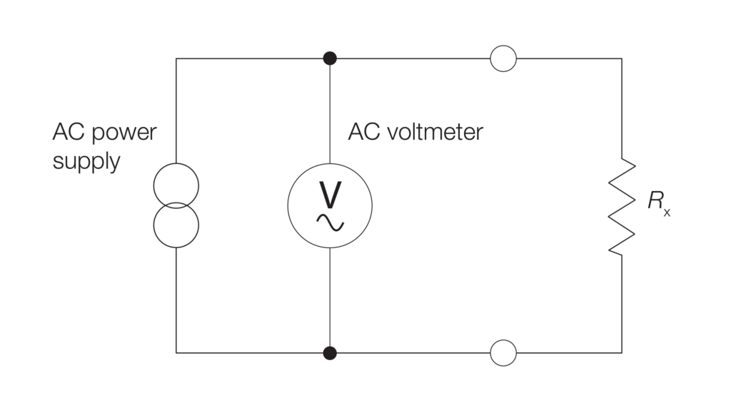
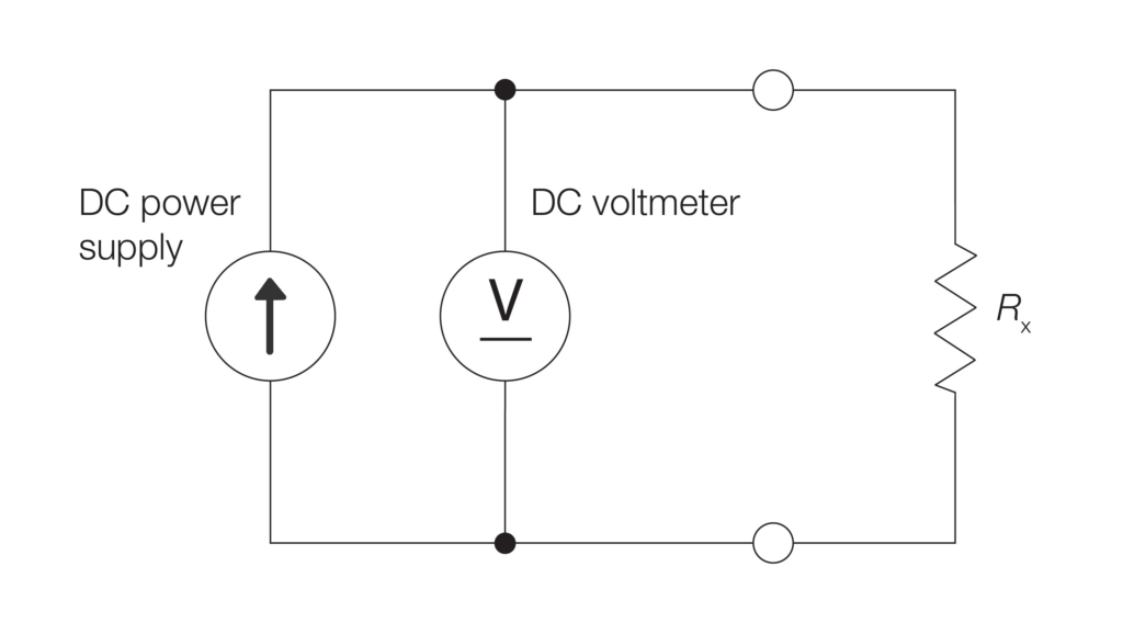
When measuring the resistance, especially on batteries, a distinction is made between two measuring methods – the AC measurement and the DC measurement. In this case, the DC resistance measurement does not refer to the DC measurement of a battery’s internal resistance, where the internal resistance is determined via the voltage change when discharging the battery with a load.
Here, DC measurement refers to measuring the resistance with a 4-wire measuring method and is used, for example, to measure the contact resistance. This method is applied in multimeters, (DC) resistance meters or insulation testers, for example. The AC measuring method, on the other hand, is used in battery testers or LCR meters.
Comparison of AC and DC resistance measurement
Comparison of AC and DC resistance measurement
Electrode testing
If you go through the manufacturing process of a lithium-ion battery in chronological order, an important DC measurement of the electrical resistance takes place quite early after the electrodes have been coated with the active material. In this process, lithium-alloyed material is applied to the electrode material under pressure and at appropriate temperatures.
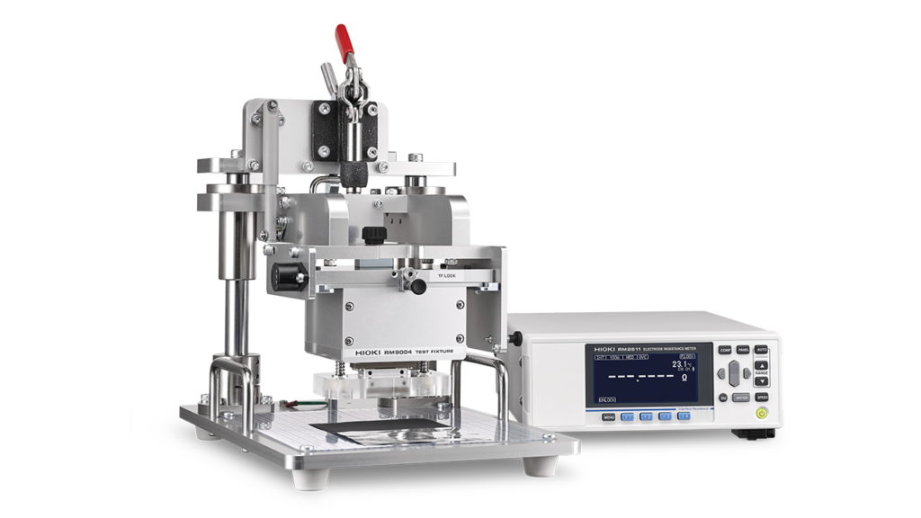
Measuring the resistance after that allows for determining the specific electrical resistance of the applied active material and the contact resistance between the active material and the electrode. Until a few years ago, however, it was not easy to determine these two values separately, whereas measuring the contact resistance between the active material and the electrode material was a particular challenge. This changed with the market launch of a new electrode resistance measurement system – the RM2610 from HIOKI.
The RM2610 from HIOKI is basically a DC resistance meter. Instead of a traditional 4-wire measurement, however, the RM2610 works with a probe in which a total of 46 spring-loaded contacts are arranged on a total area of 1 mm². During the measurement, a series of DC resistance measurements are performed between the contacts. Based on these measurement results, the resistivity of the active material and the contact resistance between the active material and the electrode are calculated with the help of a mathematical model and known parameters.
The known parameters are quantities that can be determined easily, such as the thickness of the electrode material, the layer thickness of the active material and the electrical conductivity of the electrode material. The anode is usually made of copper, while the cathode is usually made of aluminium. Copper cannot be used as a cathode material, because it would corrode at the cathode. Aluminium in turn, is unsuitable as an anode material because it reacts with lithium.
Even though the RM2610 is now often used as a tester in the production of lithium-ion cells, it was actually designed for use in development departments. The aim was to shorten the development process of cells with new materials by allowing developers to make a statement about the expected quality of the finished cell already after the coated electrodes have been manufactured. This was so unique and such an improvement of the process that HIOKI‘s electrode resistance measuring system was used by several dozens of customers in Asia while it was still in the prototype phase.
Electrode Resistance Measurement System RM2610
Resistance of welding joints
When determining the contact resistance of welding joints, the traditional 4-wire DC resistance measurement method is used. Regardless of whether these welding joints are intended to attach power terminals to a pouch cell or to connect a cell to a busbar – the contact resistance should always be checked afterwards to avoid introducing resistance-dependent heat sources at these points.
4-wire DC resistance measurements can be made with almost any digital multimeter for laboratory use or industrial use. However, when measuring the contact resistance in production, there are some important reasons to make the measurement with a resistance meter that is specially designed for this purpose.
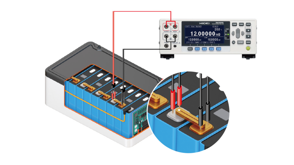
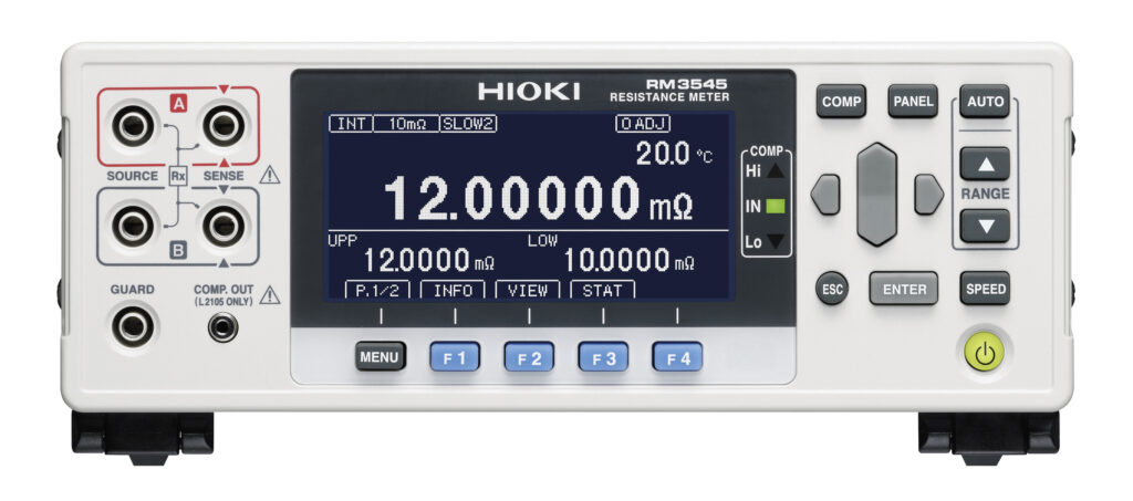
The first important reason is the measuring range for the resistance. With a common and undoubtedly premium digital multimeter showing 7 ½ digits from one of the well-known manufacturers, the smallest resistance measuring range is 1 Ω. This sounds impressive at first, but the contact resistance of welded contacts for lithium-ion batteries should ideally be below 0.1 mΩ. HIOKI‘s RM3545resistance meter easily meets this requirement with its smallest measuring range of just 10 mΩ at a resolution of 0.01 µΩ.
Resistance measurement on welding joints – RM3545
High testing speed for production
In addition to a very small measuring range, HIOKI‘s RM3545 has another function that is very useful in the production environment, which is checking the probe contact between the measuring device and the device under test during measurement: Here, the principle of 4-wire measurement is used to monitor that all 4 measuring contacts remain properly applied to the device under test during the measurement. This contact check function prevents measurements from being evaluated as “failed” due to incorrectly applied measuring contacts, and thus prevents flawless products from being sorted out erroneously.
Another very important reason for using a special resistance meter is the measuring speed: When the RM3545is set to the fastest setting, the time between the start of measurement and the output of the measurement result is only 2.2 ms. This allows for conducting many contact measurements with only a few measuring devices and is therefore ideally suited for the numerous welding joints that need to be measured in a battery production line.
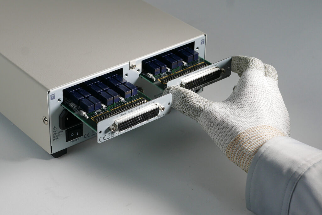
At this point, readers with production experience have any right to object that the mechanical transport of a device under test takes much longer than a few milliseconds, which clearly puts the advantage of a very high measuring speed into perspective in the overall context. To make effective use of the high measuring speed for production, HIOKI offers the RM3545-02 – a device variant with slots for multiplexer cards.
Resistance Meter RM3545
By adding two of the optionally available multiplexer cards, a single resistance meter is enabled to carry out up to 20 different 4-wire measurements one after the other in the shortest possible time when the devices under test are mechanically fed to the measuring device “in groups”. If this number of measuring channels is not sufficient, e.g. because all welded contacts of an entire battery module should be measured in one step, there is still no need to operate several RM3545units side by side, whereas their parallel control would make the integration significantly more complex.
Multiplexer slots for use in production - RM3545-02
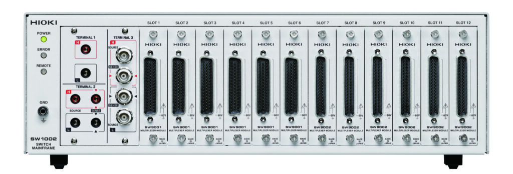
In this case, the use of a separate multiplexer system is recommended. HIOKI offers such a system in various versions, and in a configuration designed for 4-wire measurements it enables the control of up to 132 channels with a single measuring device such as the RM3545(configuration: SW1002+ 12 × SW9001). The multiplexer unit is not limited to the use with resistance meters, but can also be used with HIOKI‘s battery testers, impedance meters or voltmeters – provided the measured voltages are below 60 V.
132 measurement channels in one measuring device
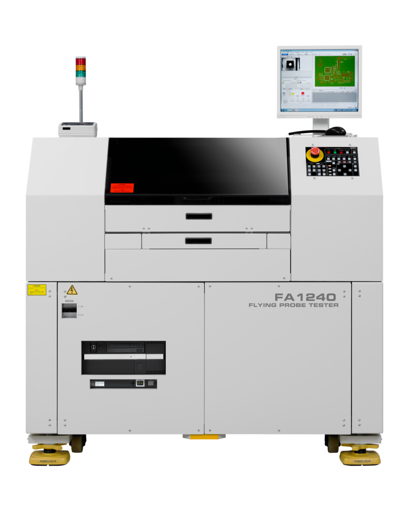
If you imagine a measurement setup with the above-mentioned 132 channels, which are used, for example, to measure the welded contacts for connections to busbars on a battery module, the 4-wire measurement method not only requires more than 500 test leads, but also more than 250 mechanical test contacts. From a technological perspective, this is possible. However, especially for cylindrical cells in a module, another solution is preferable – a flying probe tester with the somewhat cryptic name FA1240-W800. These devices are commonly used for testing assembled PCBs, and are capable of performing 4-wire resistance measurements, among other things, in as fast as 25 ms per test. After all, it does not matter whether the device under test is an assembled PCB or a battery module where welding joints are measured.
Measuring welding joints using a flying probe tester
The use of a flying probe tester in the example of measuring welding joints of battery modules has another advantage over the arrangement with fixed test contacts – be it in the variant described above or alternatively with a “bed of nails”; because while the test positions are always the same on assembled PCBs, they always deviate slightly from each other on battery modules with hundreds of cells due to production tolerances. However, the welding joints must be measured precisely.
Therefore, the FA1240 flying probe tester allows for loading a position file for each battery module beforehand. This file can be created individually for each battery module with the right camera and a suitable analysis software. Measurement errors due to mechanical production tolerances are ruled out in this way.
Battery tester for welding joints?
A common question HIOKI is often asked is whether an existing battery tester can also be used for measuring contact resistances. There is one technical reason in favour of it, but there are also several more significant reasons against it.
One reason for using the AC measuring method provided by the battery tester for measuring contact resistances is that the electromotive force – also known as electromotance – plays no role in this measuring method. To put it simply, the electromotive force is a DC offset that occurs when different metals make contact. However, for an AC measurement the DC offset can be ignored.
This electromotive force is a very small voltage that has no measurable influence on the resistance measurement in the ohm range. The contact resistance, however, is definitely in the microohm range, and here even the smallest DC offset becomes relevant for the measurement result. At this point it is important to note that the above-mentioned DC resistance meter RM3545has an offset voltage compensation function, which helps minimising the influence of the electromotive force.
One argument against the use of battery testers for measuring contact resistances is the eddy currents that can occur in the measuring leads during a 4-wire measurement, even at measuring frequencies of 1 kHz. As for the electromotive force, these eddy currents have no significance for larger resistances – but for the very low contact resistances they do have an influence on the measurement result.
The difficulty here is that eddy currents can have different magnitudes for the same device under test, depending on how the measuring lead is routed. If, for example, the test lead is guided past a (magnetic) steel sheet such as a housing, this can produce a different measurement result than if the test leads are routed in a slightly different way with the same device under test.
This is one reason why it can be difficult to obtain repeatable or precisely comparable measurement results when measuring the contact resistance with a battery tester.
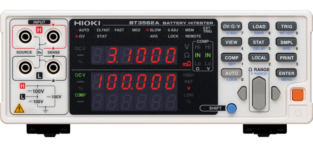
The de facto standard in battery production – BT3562A
Another reason arises when comparing the accuracies of the two measurement methods: One of the most widely used battery testers in the production environment is HIOKI‘s BT3562A. This battery tester’s basic accuracy for resistance measurement is 0.5 %. This is a very good value for an AC resistance meter. A DC resistance meter like the RM3545, however, has a basic accuracy of 0.006 %.
Pair matching of cells
At the beginning of this text we said that not only small but also equal resistance values are decisive for the quality of a battery. Equal resistance values are particularly relevant for cells that are connected together in modules and packs.
When battery cells are connected in series, a single cell with a larger resistance would be a bottleneck for the entire system. The greater resistance would not only cause an increased temperature in the array, which would have a negative impact on the service life. This cell would also be discharged faster than the others. In common applications, a battery management system ensures that these deviations among cells are compensated for and are not noticeable to the regular user.
However, the situation is different if the battery is not only used for a regular electric vehicle, but for a championship racing car, for example. Or if an appropriately designed battery provides the entire power supply for an expedition vehicle. In both cases, it is beneficial to rule out any potential deviations between the individual cells being used.
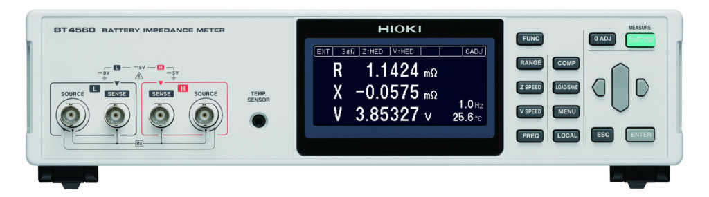
This can be achieved by pair-matching the individual cells. The impedance of the individual cells is determined by electrochemical impedance spectroscopy at different frequencies. The impedance values, consisting of the ohmic resistance and the reactance, are combined to form a Nyquist plot for each cell. If these Nyquist plots are laid on top of each other, the cells whose Nyquist plots match the most can be combined to form a module or pack.
Electrochemical Impedance Spectroscopy (EIS) with the BT4560
HIOKI‘s BT4560 battery impedance meteris also ideally suited for these measurements, because the formation of the eddy currents described above is minimised during the measurement by applying a 4-terminal-pair measurement.
Conclusion
To summarise, we can point out that the appropriate measurement technology is required especially for realising high-performance batteries. Each individual production step plays a critical role in the overall result of the battery.
For HIOKI, the close cooperation with leading battery manufacturers over decades is a guarantee for strengthening the battery market with both established and newly developed measurement technology.