Determining the impedance of a battery using the AC-IR method contains certain risks that affects the accuracy of the measurement. A quite significant risk are eddy currents, and noise induced into the measurement wiring:
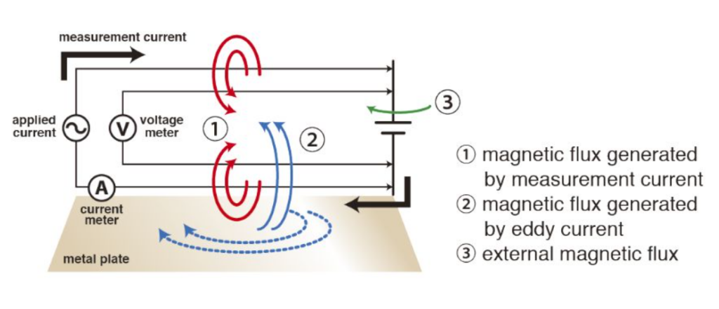
Figure 1: Four-terminal method
Using a 4-point-probe measurement for the AC-IR method, the measurement current is applied through separate wires to those which are used for voltage measurement.
Having a conducting object close to the measurement wires leads to a loss of energy due to eddy currents and thus, change of the measurement signal. Even more complicated, the effect of eddy currents usually increases quadratically with increasing frequency and by that, won’t remain constant over the whole impedance measurement range. Furthermore, induced voltage due to alternating magnetic fields in the vicinity of the testing setup will increase the noise level of the measurement.
Both leads to a distortion of the measured signal and therefore, to a wrong result when determining parameters from the Cole-Cole plot. During an experiment with fixed frequency of 1kHz, you can see the quite significant impact of eddy currents in a video from my colleagues in Japan. But take a look yourself (the eddy current part starts at around 3:09):
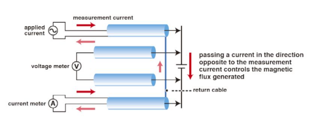
To prevent that, HIOKI has developed the 4-Terminal Pair leads at which the measurement wiring is shielded.
By leading the measurement current back through the shielding of the cables, the magnetic field around the measurement wires is levelled out, as illustrated in the diagram below. The voltage wires are also shielded, preventing noise induction with the shielding connected to ground.
Figure2: Four-terminal-pair method
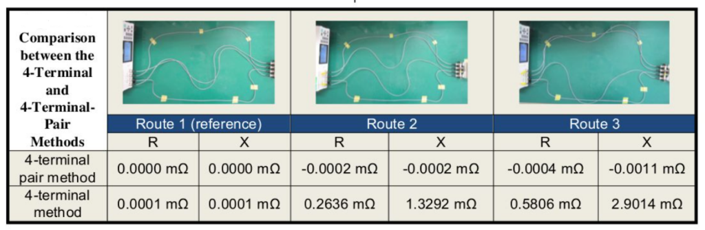
Using the 4-terminal pair probes L2002 and L2003, they show good results compared to conventional probes. At internal tests the impedance of the same battery is tested using three different wiring position:
Figure 3: Comparison between the 4-terminal & 4-terminal-pair methods
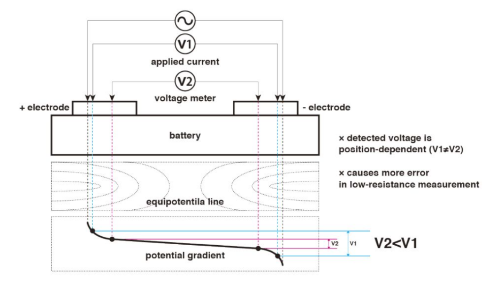
Beside induced influences on the measurement, a contacting situation with a maximum repeatability is required. This can be an issue due to the nature of a 4-point-probe measurement: applied current introduces a respective electrical potential field into the electrical contacts of the battery which is then measured by the voltage probes. As the potential fields’ shape is correspondent to the geometrical dimensions of the DUT (device under test), the value of the measured surface potential fluctuates depending on the exact position of the probes. The below graph illustrates that relationship with a four point probe measurement on a battery. The voltage of the same battery is measured on two different locations leading to different voltage readings V1 and V2:
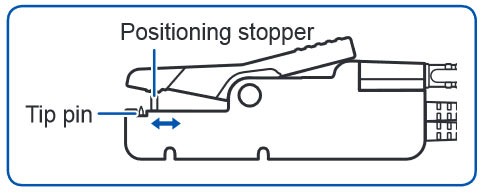
Figure 4: Effects of current terminal and voltage terminal contact position
From that it is quite clear that while the distance in between current and voltage pins impacts the measured absolute voltage value, for the repeatability of the readings it is most crucial to hit the exact same spot every measurement.
For that purpose HIOKI designed its L2002 leads with a flexible stopper to assure the measurement location is the same for each measurement and done at a defined position:
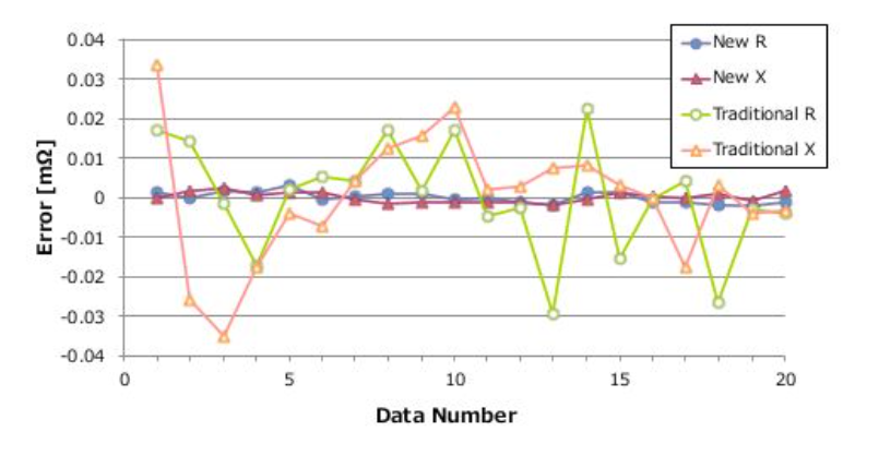
All of the test lead improvements, result in a highly increased measurement accuracy, as you can see on these 20 subsequent repeated measurements with re-contacting on a sample of 1.4 mOhm using the L2002 test leads:
Figure 5: Repeatability comparison between traditional clip probes and newly developed clip probes
Do you need support on what is best practice for testing batteries in the production line and how to avoid unnecessary problems?
Then check out our YouTube webinar recording, where we discuss the challenges of utilizing sensitive measuring instruments in battery production lines. Discover valuable tips and tricks for achieving precise, dependable, and consistent measuring results, offering peace of mind.