The increasing deployment of SiC and GaN semiconductors in power electronics lead to higher switching frequencies. As a result, smaller and lighter coils can be used in power converters. This also puts major challenge for measurement technology that you need to improve efficiency. Conventional power analyzers produce inconsistent and even incorrect measurement results when analyzing coil loss at the high switching frequencies. The key to easily obtain accurate and repeatable results is automatic phase shift correction. HIOKI makes this possible by perfectly synchronizing the power analyzer with our current sensors and high voltage dividers.
WPT – Electric cars will soon be charged wirelessly
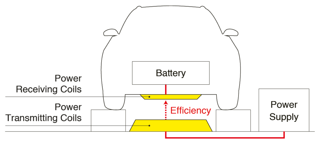
Increasingly higher switching frequencies are a general trend in many areas of the electrical industry. Especially in electromobility. One example is the development of SiC-based inverters. Another is research in the field of wireless power transmission (WPT). In the future, the batteries of electric vehicles will be charged just like an electric toothbrush or a cell phone, conveniently via charging coils installed in parking lots or even in the streets. Such wireless charging technologies will further increase the convenience and acceptance of electric cars. This can be made possible by inductive charging technologies based on magnetic resonance or magnetic induction. The development efforts of more efficient wireless charging systems are running at full speed at car and EV charger manufacturers. One crucial area to achieve higher efficiency is to analyze and reduce the losses in the coils of these WPT systems.
Figure 1: Reducing coil loss is the key to increase WPT system efficiency
Precise measurements of parameters such as voltage, current, power factor and harmonic distortion, enable engineers to better understand the performance of transmitting and receiving coils in a WPT system to ensure efficient and reliable energy transfer. Accurate, speedy assessment of input and output power as well as losses during contactless transmission increases the system performance and speeds up the development process.
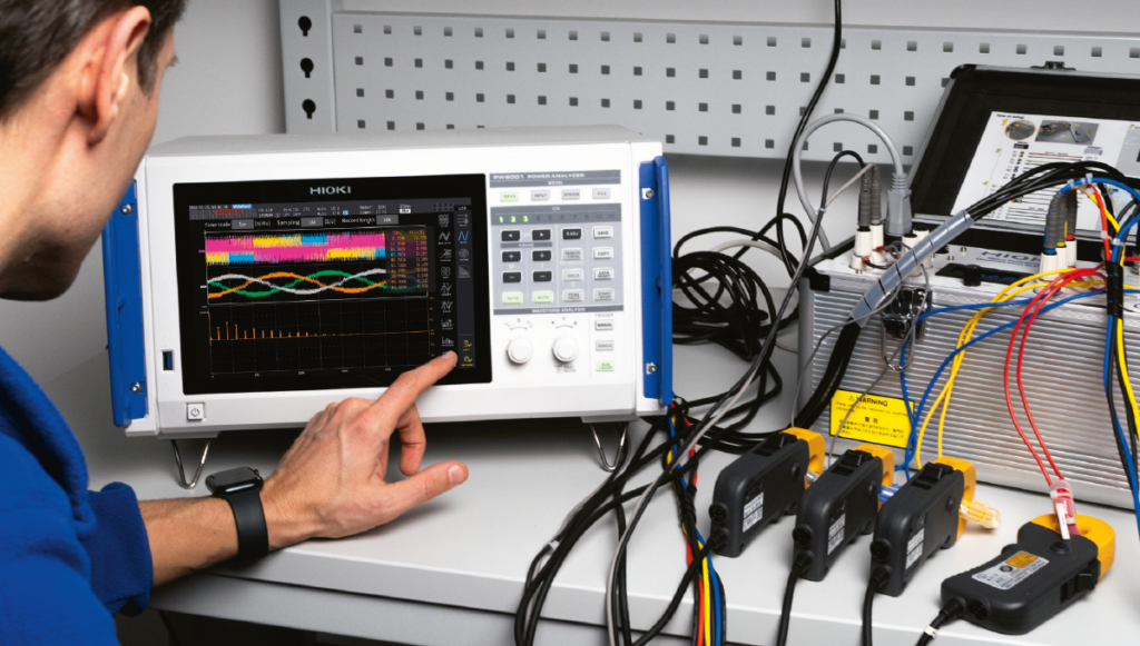
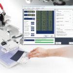
Figure 2: Accurate and efficient: PW8001 and perfectly aligned current sensors
Coil loss measurement in seconds
To date, the focus of development engineers in the design of WPT has been on minimizing the switching and conduction losses of the semiconductors in the system. To increase system efficiency even further, it is also important to use the optimal coils in the system. It is therefore important to analyze the coil losses under operating conditions. A commonly used method to measure coil losses is the Calorimeter. This method is accurate, but it has one major disadvantage: the test can take up to half an hour.
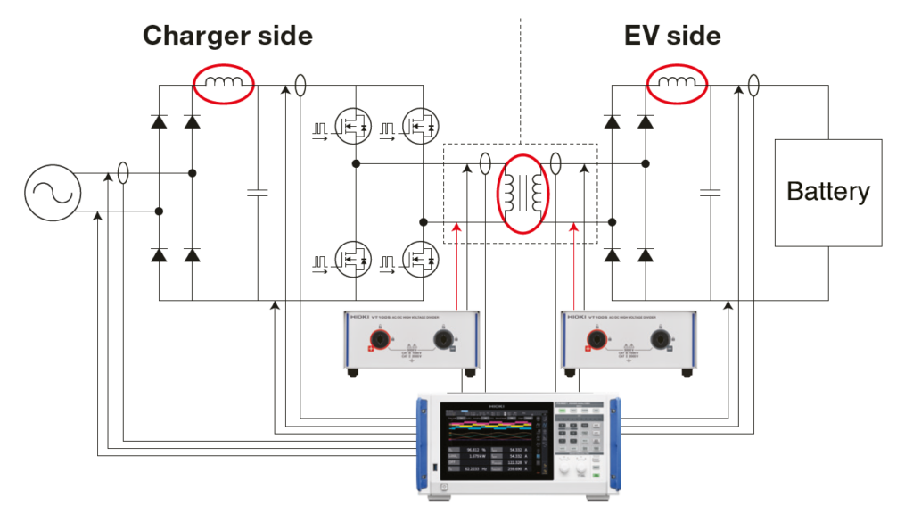
Alternatively, a Power Analyzer can be used to determine coil losses in just seconds. But this is easier said than done, as it is a challenging measurement. Below is the basic electrical diagram of an EV WPT system shown with the system coils circled in red (figure 3). Using the PW8001 Power Analyzer combined with HIOKI current sensors and voltage dividers, overall system efficiency and coil losses can be accurately determined thanks to several unique features.
Figure 3: WPT efficiency testing with a Power Analyzer: Switching Frequency 85 kHz, Output Voltage 3,000 V
The Two-Coil loss measurement with a power analyzer
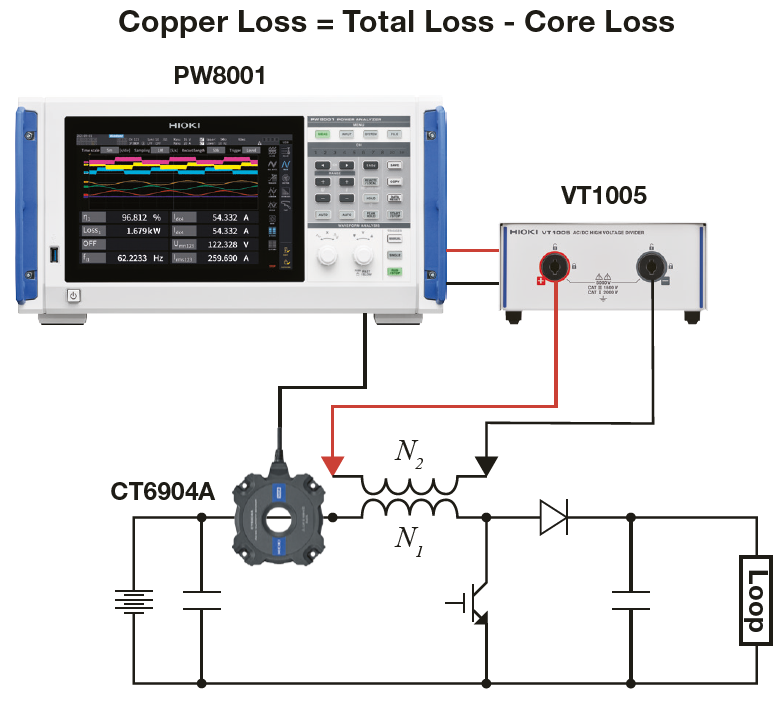
To determine the loss of a coil the so called “Two Coil Measurement” is used. With this measurement the total loss of the coil and the core loss can be determined by measuring the current flowing through the coil and the voltage over both the primary and the secondary coil. The measured values for voltages, current and phase angle etc., are the basis for the loss calculation. The coil loss calculation is done using the standard UDFs (User Defined Calculation Functions) inside the PW8001, based on which the total loss and core loss can be calculated. The copper loss is then easily determined by subtracting the coil loss from the total loss.
Figure 4: Principle of two-coil loss measurement
Accurate coil loss measurement
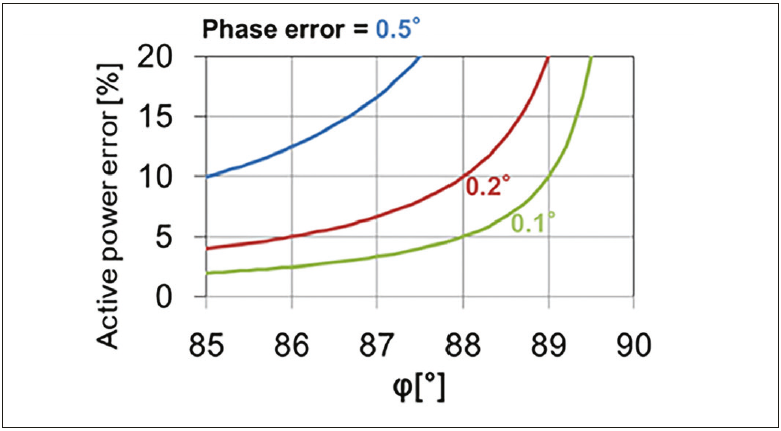
It is quite a challenge to accurately measure the loss of a coil accurately. To ensure useful results, it is recommended to measure the losses in actual working conditions, so for WPT this means at currents up to 500 A and a voltage at the receiving coil of 3 kV. The use of a high voltage divider is necessary to handle these high voltages. The power factor of the coils is extremely low. Due to this characteristic the influence of the phase error on the measurement result is extremely high, as is shown in figure 5 below.
Figure 5: At a phase angle of 88°, a phase error of just 0.2° will lead to a 10 % error in active power!
Beyond 10 kHz, conventional power analyzers measure inaccurately
The test results of traditional power analyzers with an internal shunt resistor, become unreliable for coil loss measurement beyond the 10 kHz threshold. Phase errors have a minimal impact up to switching frequencies of approximately 10 kHz. However, beyond this threshold, many power analyzers yield inaccurate loss results due to inaccurate determination of the phase angle between the voltage and the current. For higher current measurements, they also utilize third-party current sensors that were never specifically designed for coil loss measurement, adding to the poor accuracy and repeatability.
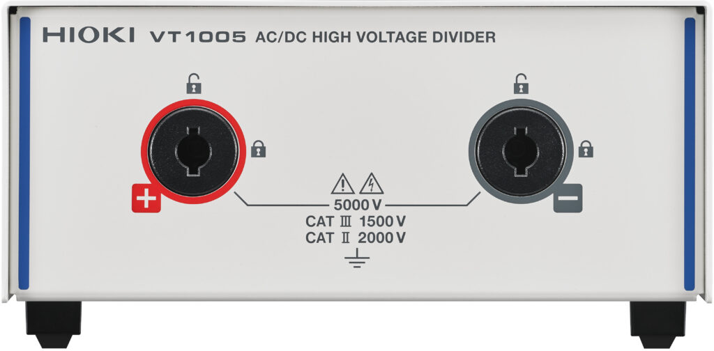
Figure 6: Accurate measurements up to 5 kV - High Voltage Divider HIOKI VT1005 with a known phase error
To overcome this challenge, the PW8001 compensates for the phase error of the current sensors and voltage dividers. For the current sensors the phase error is compensated even automatically by the PW8001, we call this unique feature Automatic Phase Shift Correction.
The Automatic Phase Shift Correction minimizes phase errors
To correct measurement errors in the phase difference at high switching frequencies, HIOKI has developed a particularly effective phase shift correction for the PW8001 power analyzer. Two conditions need to be met for this to function reliably:
a power analyzer that performs phase correction correctly,
a zero-flux current sensor with a known time delay.
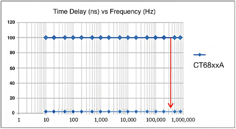
Figure 7: Stable time delay of the HIOKI CT68xxA current sensors
The phase shift correction is comparable to the familiar deskew function in oscilloscopes: if two different signals arrive at the oscilloscope with a time shift due to latency, the deskew function eliminates the signal offset by compensating for the latency with a fixed time value. The phase error is directly related to the time delay of the current sensor. For a current sensor of the CT68xxA series from HIOKI, for example, the delay is shown in Figure 8. You can see the time delay in nanoseconds depending on the frequency.
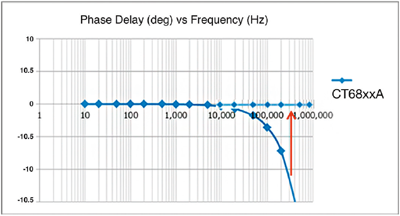
Figure 8: Phase delay in degrees over the frequency
Important to know: A delay of 100 ns at 100 Hz does not have the same effect as a delay of 100 ns at 1 MHz. This becomes clear when the time delay is converted into the phase delay (expressed in degrees) as above.
The ideal route to maximum precision
HIOKI has developed its zero-flux current sensors together with its Power Analyzers for a good reason: It’s the solution to precision and reliability. In order to efficiently compensate for phase delay, the time delay of the current sensor must remain constant regardless of the frequency. In addition, the most important key figures of the current sensors are automatically transmitted to the Power Analyzer as soon as current sensor is connected and the phase error of the current sensor is automatically compensated. And there you have it: Coil loss measurement. Accurate. In seconds.