Do you remember the “flux capacitor” that Doc Brown invented in “Back to the Future”? It was the core component in that iconic DeLorean which – after supplying it with 1.21 GW of energy – would allow Marty McFly to travel through time.
The “flux capacitor” in that classic movie of course is a work of fiction – but it definitely sounds sophisticated and actually pretty cool. The “zero-flux” in HIOKI’s “zero-flux current sensors”, on the other side, is neither a work of fiction nor a cool-sounding term invented by HIOKI’s Japanese marketing team.
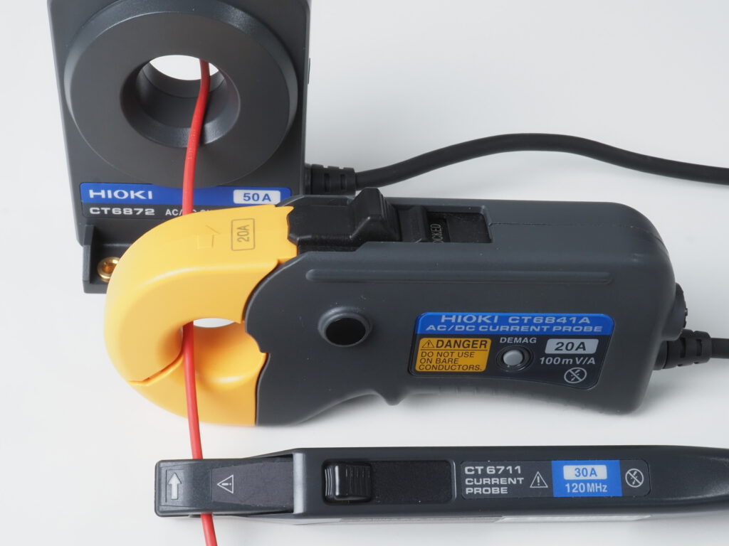
Various HIOKI "zero-flux" current sensors
Lets look at what "zero flux" actually means by starting with "flux":
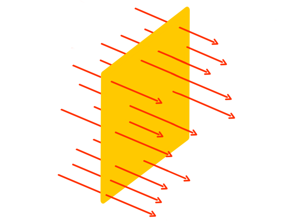
The term “flux” is widely used across various scientific and engineering fields, each with a specific definition tailored to its context. However, the core idea behind all these definitions is the concept of a flow through a surface or an amount of something passing through a specific area.
Flow through a surface
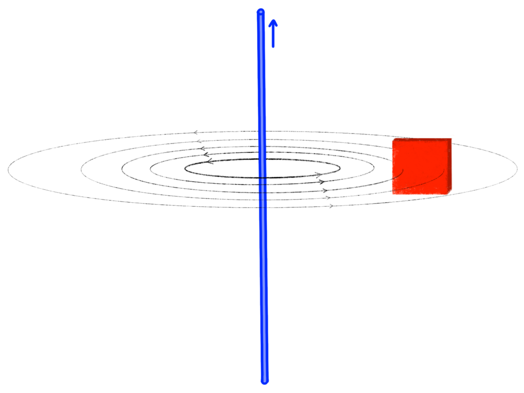
Since we are talking about current sensors, magnetic flux is the relevant type of flux. Magnetic flux refers to a measure of the quantity of magnetism, taking into account the strength and the extent of a magnetic field. Essentially, it represents the magnetic field’s presence, strength, and orientation through a specified area.
Magnetic field through a specified area
Next, lets look at how a traditional current transducer works:
The reason why we look at this technology first is because flux plays a key role in this sensing method as well and it’s a bit like a “prequel” of a zero flux current sensor.
Current sensors using this classic transducer principle for current detection are limited to AC. They are not the most accurate current sensors, but making them is not an overly complex procedure. A typical current sensor like this can be found in AC clamp meters that live in the tool bag of maintenance technicians for electrical installations.
.
AC Current Transducer (CT) sensing method
A classic AC current transducer works pretty closely to a transformer – only that the number of windings on the primary side is just one: The primary or measured current induces magnetic flux (Φ) into the magnetic core of the current sensor. This induces a secondary current into the coil (N), which flows through the shunt resistor (r). The flow of this secondary current induces magnetic flux into the magnetic core of the current sensor in the opposite direction (Φ’). Essentially, this is a negative feedback mechanism and the coil (N) is a feedback coil.
The magnetic flux generated by the measured and secondary currents ideally balance out each other completely. This ensures that the magnetic core does not become saturated. This is crucial to maintain the sensor’s accuracy and overall functionality. If this balancing act worked perfectly, then this would already be a “zero flux current sensor” as the measured magnetic flux (Φ) and the opposing secondary magnetic flux (Φ’) would be the same. Unfortunately, they are not the same for lower frequencies.
Zero-Flux current sensors
For high frequencies the secondary magnetic flux (Φ’) balances out the magnetic flux of the measured current (Φ) very well. For lower frequencies or even DC the story is quite different – because like with transformers, these current transducers require AC to work. Therefore, an additional mechanism needs to be integrated to also balance out the magnetic flux for lower frequencies or DC.
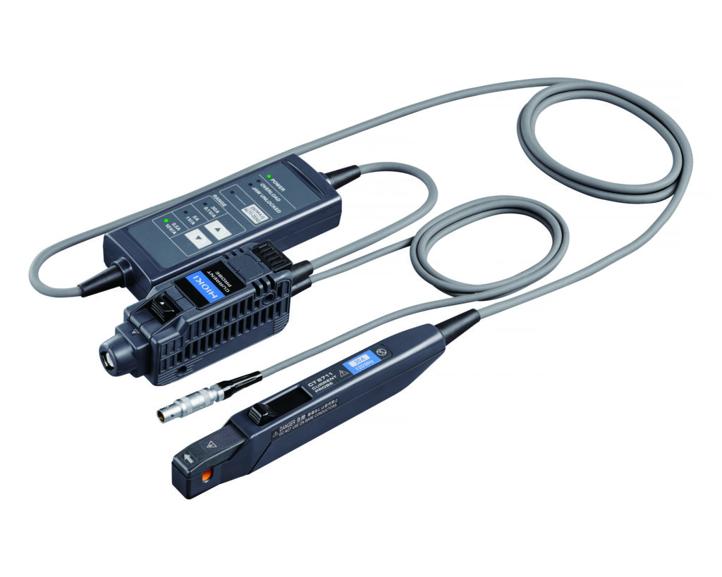
HIOKI CT6711 Zero-Flux current sensor from DC to 120MHz
With this additional mechanism a current transducer can become a zero-flux current sensor. Basically, there are three different mechanisms that can be added to take care of the low frequency currents and DC:
Detection Coil (not for DC!)
Hall Element
Fluxgate
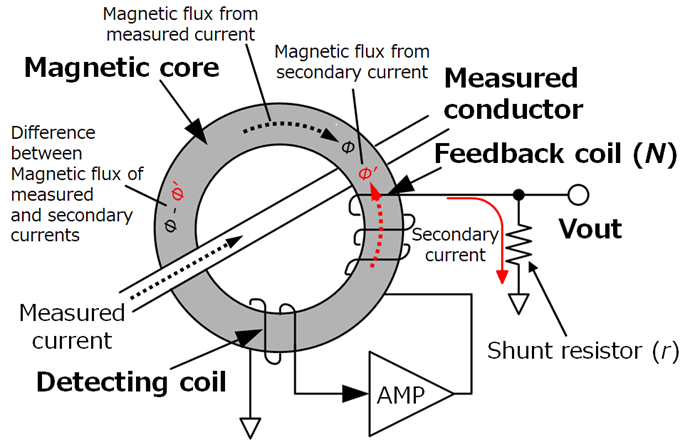
As it is the most simple mechanism and also the closest to the above current transducer principle, let’s use the detection coil principle as example for a zero-flux current sensor. This principle is not suitable for DC currents, as it is based on another coil – but it allows for zero flux for AC currents from very low to very high frequencies.
Zero-Flux current sensor with detecting coil
For higher frequencies, the current sensing principle of this zero-flux sensor is the same as the one used in a classic current transducer. In fact, regardless of which mechanism is used to handle low AC frequencies or DC, the current sensing principle for the higher frequency currents in a zero-flux sensor is always based on a feedback coil.
For low frequencies, the remaining magnetic flux (Φ-Φ’) induces current through the detecting coil. Based on this, an additional negative feedback current is added through an amplifier circuit into the feedback coil. This properly balances out the magnetic flux (Φ-Φ’) also in the low frequency regions and zero flux is achieved.
As a conclusion, despite the cool sounding and rather sophisticated name, a zero-flux current sensor has nothing to do with time travel. It has, however, the ability to accurately sense currents from DC or very low frequencies to high frequencies.