Some time ago HIOKI created a short video in which we briefly compared hall-sensor based current sensors with fluxgate based sensors:
In the video I said that “every hall sensor in the world has a DC drift” and therefore is not suitable for power measurements as this drift affects the accuracy of the measurement.
But what does “DC drift” mean? Does it mean that after 20 seconds into the measurement the measured value starts to drift away? Does it mean that after half an hour it has drifted away so much that the measured value is 20% higher than it should be?
But what does "DC drift" mean?
Does it mean that after 20 seconds into the measurement the measured value starts to drift away? Does it mean that after half an hour it has drifted away so much that the measured value is 20% higher than it should be?
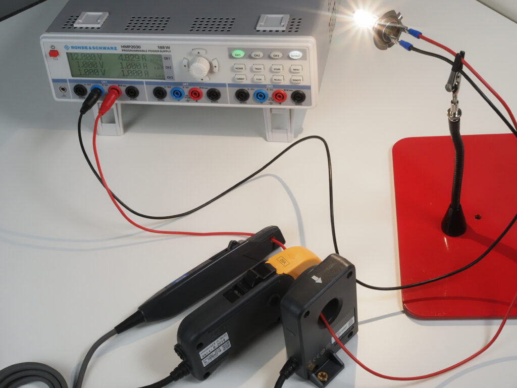
To show what DC drift in a hall-sensor based current probe means, I took a DC power supply, connected a 50 watts car light bulb with a supply voltage of 12V and picked a hall sensor based current probe as well as two fluxgate based current sensors for a comparison.
Figure 1: An old-school H7 car light bulb powered by a Rohde & Schwarz HMP2030.
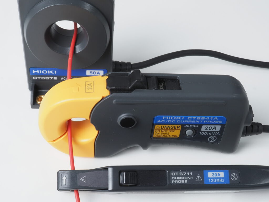
These were the current sensors chosen for this comparison:
HIOKI’s CT6711 is the flagship model in the portfolio of wideband zero flux AC/DC current probes. It is hall sensor based, features a bandwidth of 120MHz, is typically used with oscilloscopes or recorders, and has three current ranges to choose from: 0.5A, 5A or 30A. With our 50W bulb powered by 12V the 5A range is perfect for our measurement
HIOKI’s CT6841A is a 20A zero flux current clamp. It is made for power measurements and uses a fluxgate instead of a hall sensor
HIOKI’s CT6872 is a 50A zero flux current sensor. Like the CT6841A it is also made for power measurements and also uses a fluxgate instead of a hall sensor
Figure 2: HIOKI's CT6711, CT6841A and CT6872 zero flux current sensors.
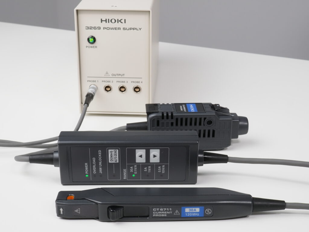
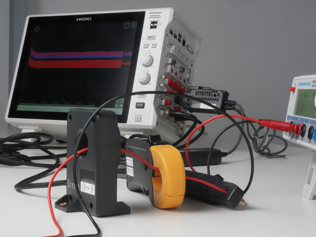
To record and compare the measured currents over a longer period of time, I connected them to a HIOKI MR6000 memory recorder. The CT6711 hall sensor based current probe has a BNC output as it is typically used with oscilloscopes or recorders. For this measurement I picked a high resolution unit for the MR6000 recorder called “8968” which offers a 16bit resolution. HIOKI’s MR6000 memory recorder has a hardware option that provides the necessary power to drive the CT6711 or other current sensors with a 2-pin Lemo power supply connector. To use the CT6711 with an oscilloscope, a power supply unit is needed like HIOKI’s 3269 or 3272.
Figure 3: HIOKI’s CT6711 with 3269 power supply unit.
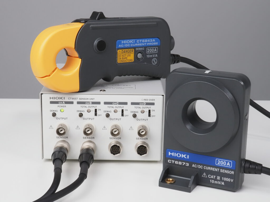
Figure 4: Fluxgate based sensors with power supply and BNC break-out.
The two fluxgate based sensors CT6841A and CT6872 come with a proprietary ME15W connector. To connect them with an oscilloscope, a power supply unit CT9555 , CT9556 or CT9557 would be required which not only supplies the required power to drive the sensors but which also outputs the measured signal to a BNC connector.
As I don’t use an oscilloscope for this test but a HIOKI memory recorder, these current sensors can directly be connected to the recorder through a current sensor module called “U8977”, which conveniently also offers a 16bit resolution.
Figure 5: HIOKI MR6000 recording the measured currents from the sensors.
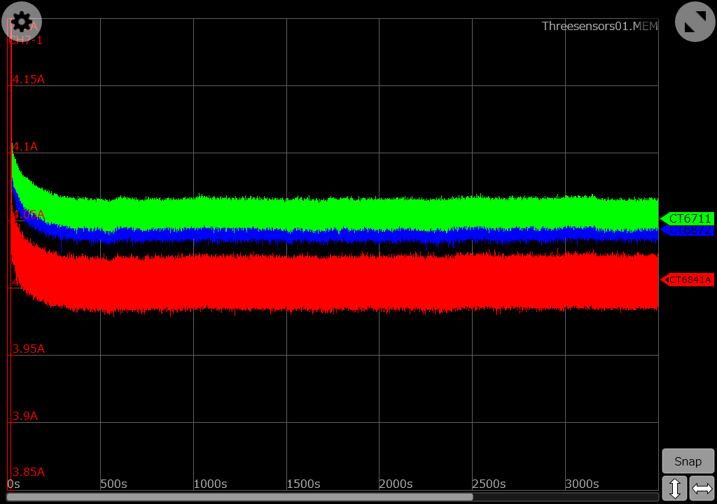
All that was needed now was to switch on the light bulb, record the current for an hour or so and show you how the CT6711 hall sensor based zero flux probe drifts away:
Figure 6: Current recording over one hour with CT6711 at front.
But as you can see there is no drift. Not at all. What you can see is that I have missed to zero-adjust the channels before starting the recording, which especially causes the CT6841A (red curve) to be displayed a little next to the other two measurement curves. While this was not intended, in this case it probably even helps to show that there are three curves on display. Because the CT6872 (blue curve) is hidden behind the curve of the CT6711 (green curve), here is the same recording with the CT6872 in front.
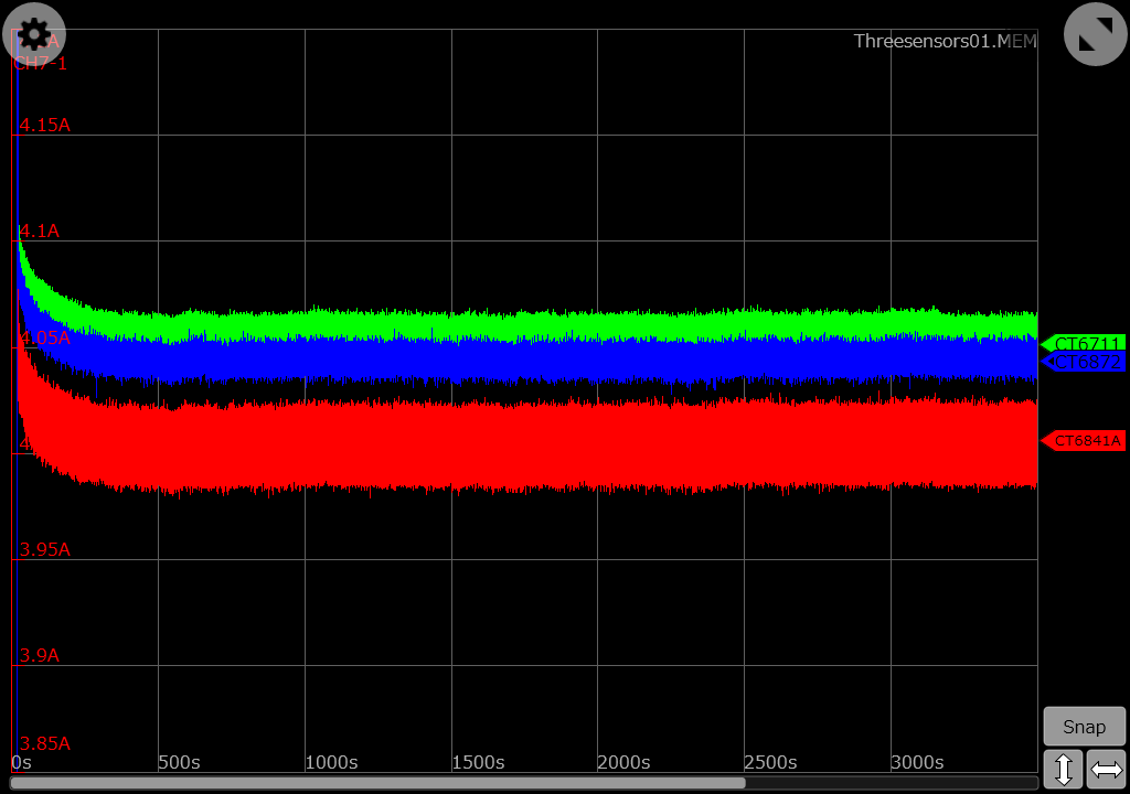
Figure 7: Current recording with CT6872 at front.
Both the CT6841A and the CT6872 are fluxgate based sensors, but the “thickness” of the curves is quite different. At this point we should remember that the CT6841A (red curve) is a current clamp while the CT6872 (blue curve) is a push-through sensor. Push-through sensors don’t have the flexibility of a current clamp but their accuracy is superior. The difference becomes even more clear when you consider that the CT6841A has a 20A range while the CT6872 has a 50A range.
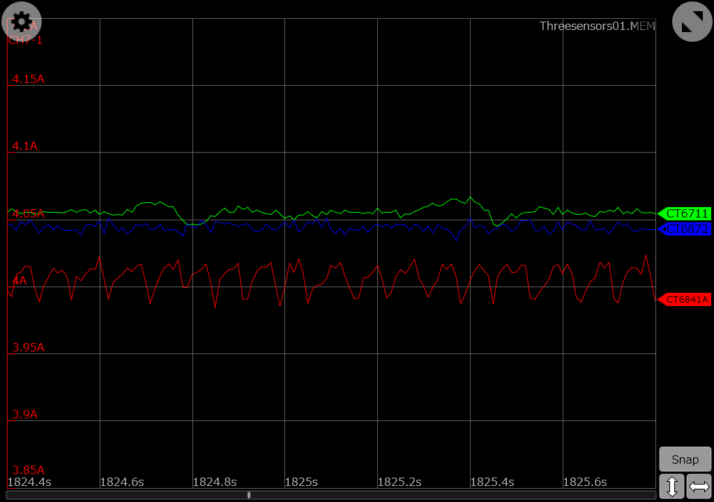
Figure 8: Zoomed into the measurement.
What we need to keep in mind here as well is that the load which is used for this experiment is a H7 car light bulb and not a precise programmable electronic load. This might have contributed to the “thickness” of the measurement curves, which in all recordings of this test have been made with only 100 samples per second (1MSa/s would have been possible). However, the “thickness” of the CT6841A curve, or the range between min and max values, is actually just around 30mA.
But again, more than one hour of recording with a hall sensor based zero flux probe, and there is no DC drift to be observed. The statement in the video was “not suitable for power measurement because those measurements take a long time”. But isn’t a measurement over one hour “a long time”?
Lets look at applications of power measurements where these sensors are typically used and which take a longer time: Especially the current clamps are very popular for WLTP measurements. Those measurements mean that the sensors get installed in cars. Not only cars, actually, but also engine rooms of cars. And what happens with sensors sitting in engine rooms when the engine is running? They heat up…
As you can see from the pictures above, the current sensors in the measurement were sitting on a desk. They were not sitting in an engine room of a car, a machine or close to an inverter where the temperature changes over time. So lets repeat the same measurement but this time simulate an environment with a changing temperature.
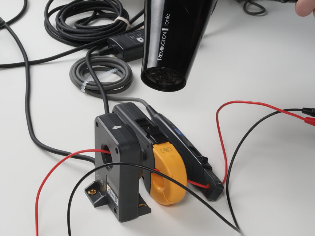
Figure 9: A hair dryer simulating a heat source.
With no climate chamber quickly available, a hair dryer turned out to be a suitable and easily available alternative as heat source. Before restarting the test I have zero-adjusted the channels of the current input module, which is the reason why the curves of the CT684A and CT6872 are now on top of each other.
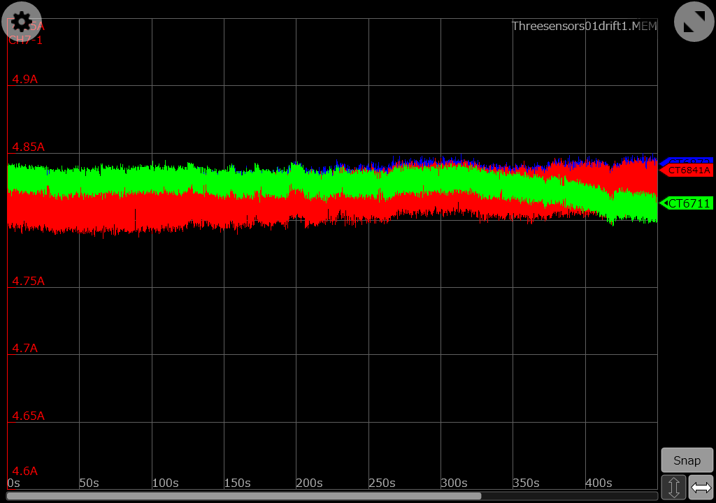
Figure 10: Changing temperature causes the hall sensor based current probe to drift.
Once the hair dryer started to warm up the sensors, there is a clear drifting visible in the measurement curve of the CT6711. The curves of the fluxgate based sensors also suggest a small drift, but the current consumption of the light bulb actually did go up during that test – probably caused by the increasing temperature. So this slightly upwards moving curve of the CT6841A and CT6872 is not showing a sensor drift but the correct measurement.
As a conclusion, time itself does not cause a DC drift in a hall sensor based zero flux probe – temperature changes are required for that drift to happen over time. However, it doesn’t mean that hall-sensor based current probes are perfect for power measurements as long as the temperature stays constant. Factors like face shift also play an important role in power measurement – especially at higher frequencies. If you want to know more about this then feel free to get in touch with us for a chat.