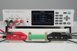
12 V lead-acid batteries can be replaced by 4 x 3 V Li-ion cells. But battery management systems (BMS) are installed in batteries like these. And they have a huge impact on the result when using a battery tester to check their state of health. Find out why.
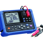
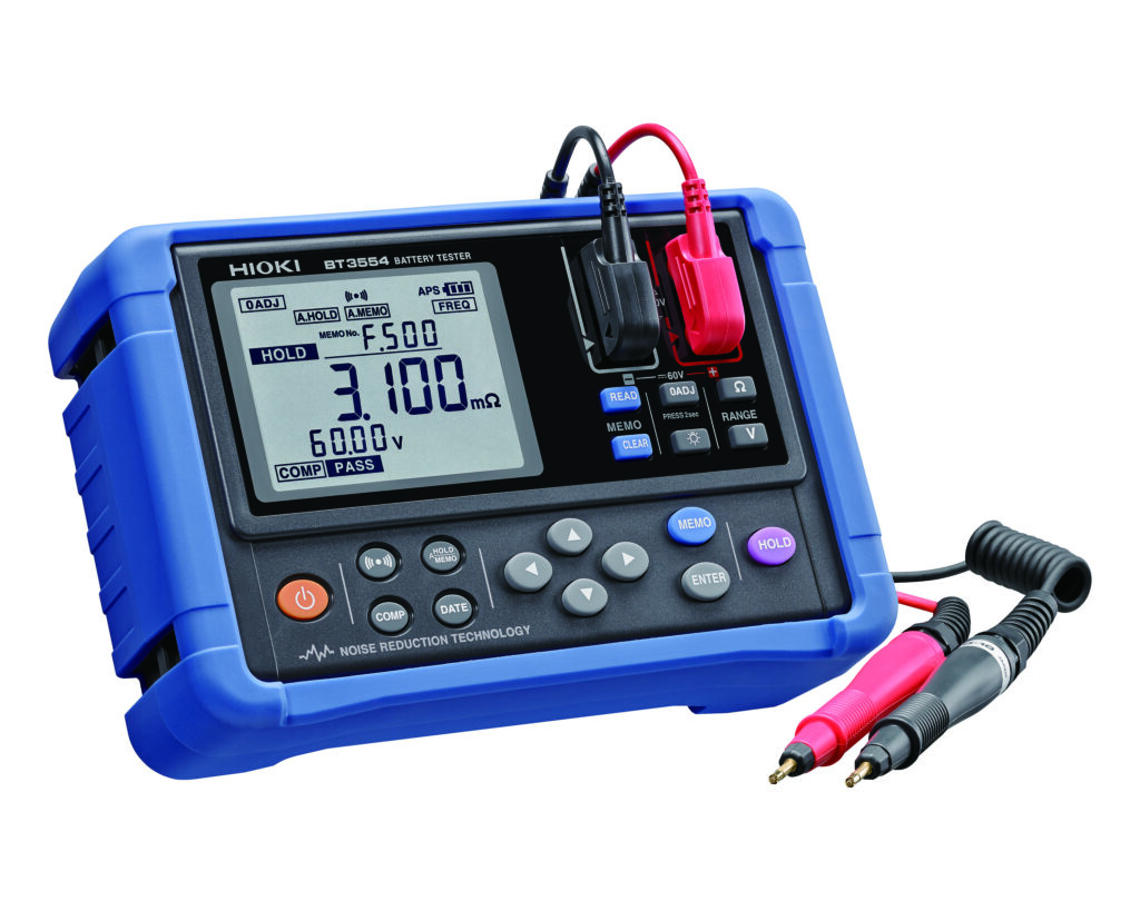
There is a not so surprising trend to replace lead-acid batteries used in all kind of systems or devices with lithium-ion batteries (LIBs). When checking lead-acid batteries in these devices or systems by service technicians then often a battery tester like HIOKI’s BT3554 is used. That raises the question whether this or any other battery tester can also be used in the same way as with lead-acid batteries. From a sensitivity point of view the BT3554 offers a 3 mOhm range – so even measuring large LIBs with very low impedances is not a problem. But unfortunately it’s not that straight forward…
Lihtium cells typically have nominal cell voltages between 3.2 V (lithium iron phosphate) and 3.7 V (lithium manganese oxide). So very often they are connected in series to provide a higher voltage. For example 4 lithium iron phosphate (LiFePo4) cells connected in series are perfect to replace a traditional 12V lead-acid battery. What you will almost always find in a series of LIB cells is a battery management system (BMS). Not only does it protect the cells from being subjected to a charging voltage which is too high or a discharge that drives the voltage too low – a battery management system will also balance the charging current between the cells. There are battery protection boards also for single cells – they obviously don’t balance anything but offer a similar protection to the cells as a BMS used in series of cells. So when you measure the LIB – regardless of single cell or series of cells – then you should consider the impact the BMS has on the measuring result. Especially when you can only access the two “output poles” of the cells connected in series.
But how much influence does such a BMS have?
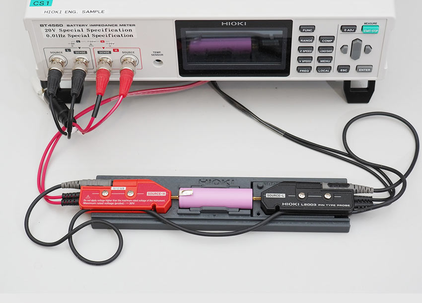
Obviously there is not the single one answer to the question but… lets have a look. I work for HIOKI so apart from things like flying probe testers I have access to most of the products made by HIOKI and when it comes to battery measurement instruments there are plenty to choose from. eBay was the source for two different kinds of BMS boards – one for single cells and one for series of 2 cells. In my recent post about temperature effects when measuring lead-acid batteries there was some criticism about me using a battery which “I had flying around” because of the unknown state of health, so for this test I got two brand new Samsung INR18650-35E cells (lithium nickel cobalt aluminum oxide / NCA) with a nominal voltage of 3.6 V. The battery tester I used is a special version of HIOKI’s BT4560 battery impedance meter. “Special version” because this one goes up to 20V while the normal BT4560 only goes up to 5V as this instrument is primarily designed to measure single lithium ion cells.
First I ran a measurement of a single Samsung cell with several dozen measurement points between 0.1 Hz and 1050 Hz:
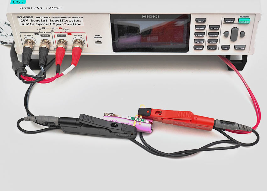
Next I added a protection board for single cells, connected the measurement probe to the outputs of the protection board and ran the same measurement again:
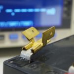
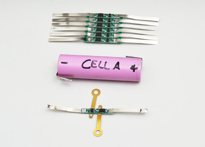
Here is an image to show you the kind of protection board I used for this test:
The usual output of such a measurement with the BT4560 is a Nyquist plot but I decided to seperate resistance and reactance values and generate two seperate graphs. Lets look at the resistance and the reactance values:
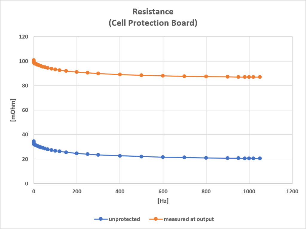
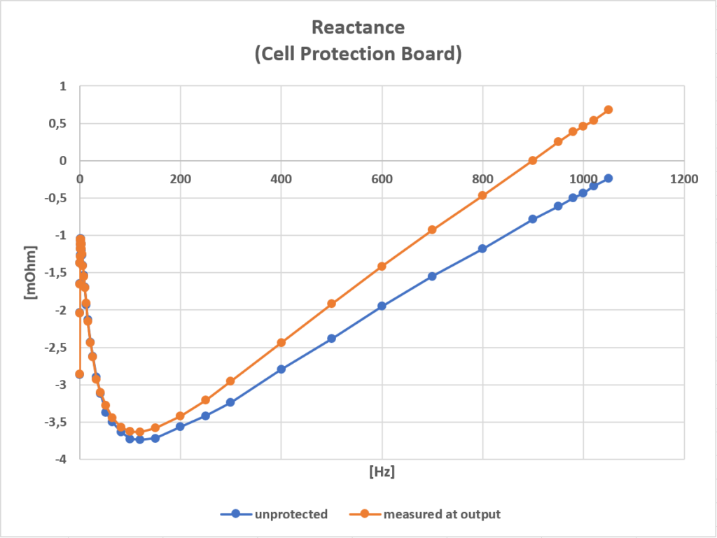
A typical test frequency used by battery testers is 1000 Hz. As you can see in the reactance chart the difference of the values with or without protection board is at around 1 mOhm at 1000 Hz. What’s interesting is the huge difference in value of the resistance: At 1000 Hz the resistance value of the unprotected cell is around 20 mOhm which is almost exactly the value I could find in Samsung’s documentation about this cell. With the protection board attached this value is four times as much. Without knowing about the protection board and its behaviour one can easily think that the battery is pretty dead with such a resistance reading. But of course it isn’t.
Now as you can see from the above images I soldered some brass pads to the protection board for an easier connection of the test probes. Last time I did this someone suggested that I commited a “capital sin” using them because of the their influence to the measurement results. I checked – and after checking I think it’s safe to say that this influence can be ignored as the impact was less than 1 mOhm.
What about the BMS for 2 cells? Same instrument, same measurement, same measurement points:
What about the BMS for 2 cells?
Same instrument, same measurement, same measurement points:
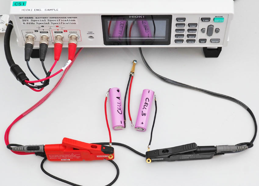
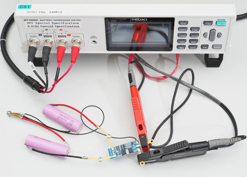
For the analysis I have created three different graphs:
- The addition of resistance and reactance values of the two seperate unprotected cells
- Measuring at the output of the unprotected cells wired together (left image above)
- Measuring at the output of the BMS board (right image above)
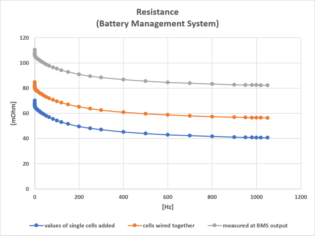
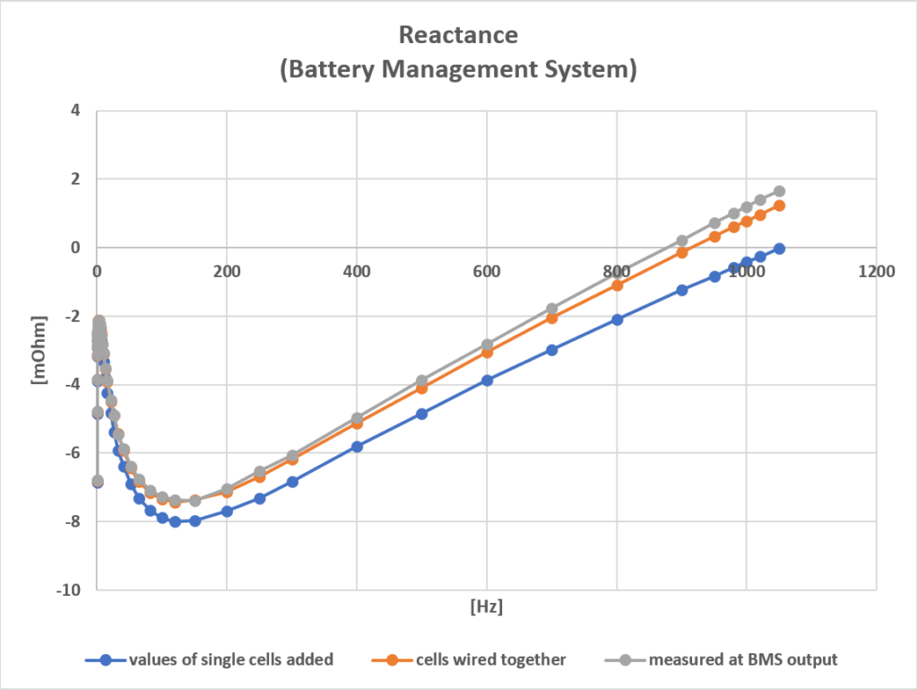
I was surprised about the large impact that the wiring made to the result of the resistance which was at around 18 mOhm at 1000 Hz and I hope that poor soldering is not the reason for it. Compared to the protection board which I used for the single cell above the impact of the BMS on the resistance values isn’t as big but then every such board has a different behaviour and I’ve never seen anyone specifying this impact in a datasheet.
So as a result:
Yes, you can use battery testers like the HIOKI BT3554 to measure LIBs but be aware of the impact of protection boards. Also don’t forget that judging the state of health of a LIB from a maintenance measurement at a single frequency is tricky and you need very good and very exact reference values for the exact cell type.
If you think I missed something or if you have questions or especially comments then please get in touch…


