We use cookies to enhance your browsing experience, serve personalized ads or content, and analyze our traffic. By clicking "Accept All", you consent to our use of cookies.
Customize Consent Preferences
We use cookies to help you navigate efficiently and perform certain functions. You will find detailed information about all cookies under each consent category below.
The cookies that are categorized as "Necessary" are stored on your browser as they are essential for enabling the basic functionalities of the site. ...
Always Active
Necessary cookies are required to enable the basic features of this site, such as providing secure log-in or adjusting your consent preferences. These cookies do not store any personally identifiable data.
No cookies to display.
Functional cookies help perform certain functionalities like sharing the content of the website on social media platforms, collecting feedback, and other third-party features.
No cookies to display.
Analytical cookies are used to understand how visitors interact with the website. These cookies help provide information on metrics such as the number of visitors, bounce rate, traffic source, etc.
No cookies to display.
Performance cookies are used to understand and analyze the key performance indexes of the website which helps in delivering a better user experience for the visitors.
No cookies to display.
Advertisement cookies are used to provide visitors with customized advertisements based on the pages you visited previously and to analyze the effectiveness of the ad campaigns.
All you needed was a precise sensor to measure DC current, and after talking to HIOKI you ended up ordering a 10MHz AC/DC current sensor… Does HIOKI employ sales magicians who can sell ice to eskimos? Or does bandwidth simply also matter when measuring DC?
When thinking of “bandwidth” in a measurement instrument the first thing that often comes to mind is the bandwidth definition of an oscilloscope. According to the standard for digitizing waveform recorders (IEEE 1057), electrical bandwidth is defined as the point at which the amplitude of a sine wave input is reduced by 3 dB (approximately 30%) relative to its level at a lower reference frequency.
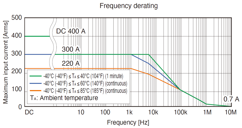
Lets look at the frequency derating curve of HIOKI’s CT6873 200A AC/DC current sensor with a bandwidth of 10MHz:
Frequency derating curve of HIOKI CT6873 current sensor
When a maximum DC input current of 400A has become a maximum input current of 0.7A at 10MHz then no degree in maths is required to quickly see that this is a reduction of more than 30%. That’s because the derating of a current sensor and the sensor’s bandwidth have nothing to do with each other.
But if bandwidth doesn’t describe the current which the sensor can handle within that bandwidth – what does it describe?
Bandwidth is a measure of the range of frequencies a sensor can accurately respond to. For a current sensor, this would involve how quickly it can detect and respond to changes in the measured current. A common way to explain the relationship between response time and bandwidth (BW) is through the rise time (T_rise), which is the time required for a signal to go from 10% to 90% of its final value:
Definition of Rise Time
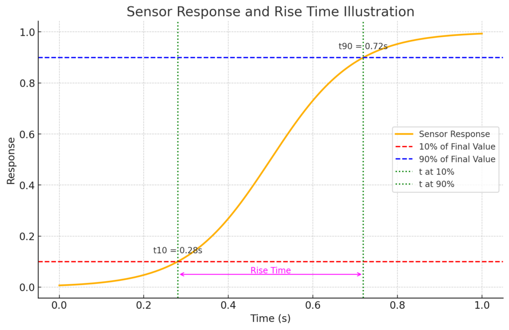
The following image illustrates the rise-time of a current sensor:
Illustration of Rise Time
The orange curve represents how the sensor’s output responds over time to a step change in input. The horizontal dashed lines mark 10% and 90% of the sensor’s final output value. These levels are key points for measuring the rise time. The rise time is the period between when the output first reaches 10% of its final value and when it reaches 90%. It’s indicated by the magenta double-ended arrow on the graph.
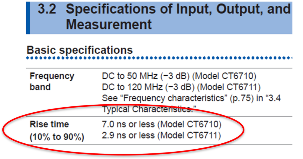
It’s important to note that the above formula does not apply to all current sensors – but in most situations the formula is correct. The following excerpt of HIOKI’s CT6710 / CT6711 describes the rise time according to the above formula:
Excerpt of HIOKI's CT6710 / CT6711 manual
Even in applications focused on DC current measurement, a fast rise time of a current sensor allows to capture transient events. Such rapid changes in current levels might be due to startup/shutdown conditions, fault conditions, or switching events in the circuit. A current sensor with a sufficient bandwidth therefore allows to precisely capture for example the inrush / surge current of a motor start.
Also, DC current measurements can be affected by high-frequency noise or interference from various sources, such as electromagnetic interference (EMI) from nearby equipment, radio frequency interference (RFI), or switching noise from power electronics. A current sensor with sufficient bandwidth can more accurately represent the true current, including the detection and potential filtering of such noise components, which might otherwise distort the measurement or go undetected with a low-bandwidth sensor.
In summary, while the primary measurement interest might be DC currents, the bandwidth of a current sensor plays a crucial role in ensuring accurate, reliable, and comprehensive current measurements across a range of conditions and applications.